Table of Contents
Introduction
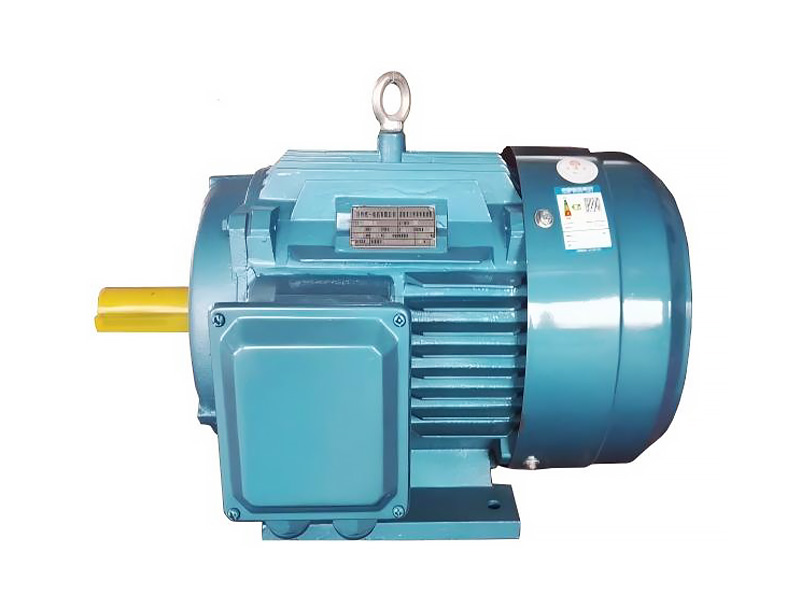
Three phase induction motors are among the most widely used electric motors in industrial equipment. Pumps, fans, compressors, conveyors, machine tools, ventilation systems, and automated production lines all depend on this motor type because it combines relatively simple construction with reliable operation across a wide range of loads.
For engineers, equipment manufacturers, and industrial buyers, understanding what is a three phase induction motor is important before comparing motor series or specifications. Rated power alone does not determine whether a motor is suitable. Voltage, frequency, pole number, speed, slip, efficiency, insulation, protection level, mounting arrangement, duty cycle, and the characteristics of the driven equipment must all be considered.
This guide explains the operating principle of a three phase induction motor, its major components, speed and slip, efficiency, common applications, and the main factors that should be reviewed before selecting a motor for industrial machinery.
What Is a Three Phase Induction Motor?
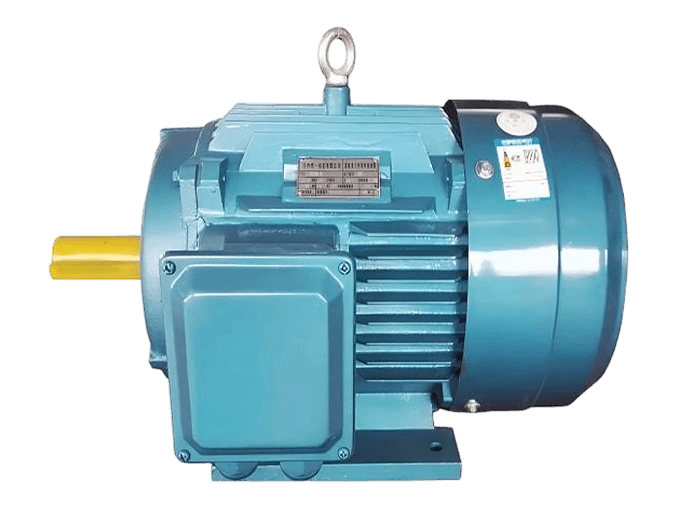
A three phase induction motor is an AC electric motor that uses a three-phase power supply to create a rotating magnetic field in the stator. This magnetic field induces electrical current in the rotor, and the interaction between the stator and rotor magnetic fields produces torque.
The rotor is not normally connected directly to the external electrical supply. Instead, the current required to produce rotor torque is generated through electromagnetic induction. This operating principle is why the motor is called an induction motor.
It is also commonly referred to as a three phase asynchronous motor. The term “asynchronous” describes the fact that the rotor normally turns slightly slower than the rotating magnetic field produced by the stator.
This difference in speed is known as slip.
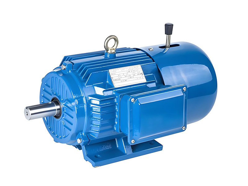
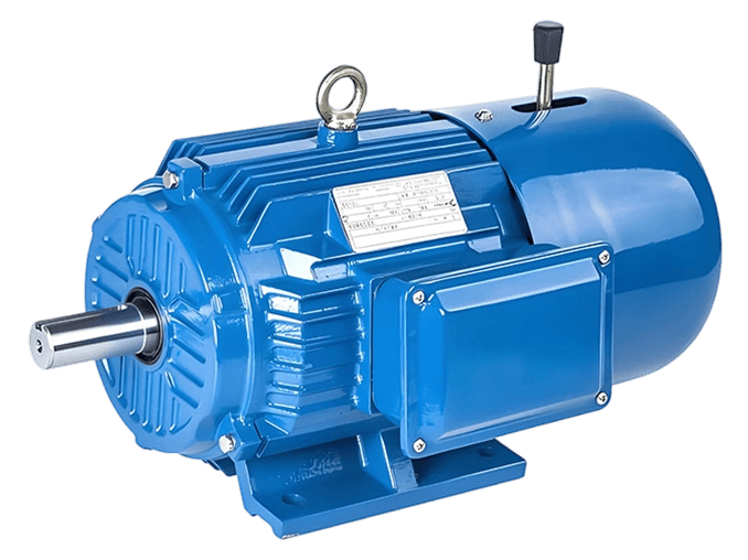
Most general-purpose industrial three phase induction motors use a squirrel-cage rotor. Its relatively simple structure avoids brushes and commutators, helping reduce mechanical complexity and making the design suitable for many continuous industrial applications.
The basic principle of an induction motor also explains why this motor technology has become common in machinery ranging from pumps and fans to conveyors and compressors.
How Does a Three Phase Induction Motor Work?
When a three-phase AC supply is connected to the stator windings, three alternating currents flow through windings positioned around the stator.
Because these currents are electrically separated in phase, their combined magnetic effect produces a magnetic field that rotates around the inside of the stator.
This rotating magnetic field passes across the rotor conductors. The relative movement between the magnetic field and rotor induces an electromotive force in the rotor. Current then flows through the rotor conductors.
The rotor current generates another magnetic field. Interaction between the rotor field and stator field creates electromagnetic torque, causing the rotor and motor shaft to turn.
As the rotor accelerates, its speed approaches the speed of the rotating stator field. However, during normal loaded operation, the rotor remains slightly slower.
This speed difference allows electromagnetic induction to continue.
If the rotor reached exactly the same speed as the rotating magnetic field, there would be no relative movement between the field and rotor conductors. Without this relative movement, the induction needed to maintain rotor current and torque would be greatly reduced.
This is why slip is a normal and necessary characteristic of an induction motor rather than simply a defect or speed loss.
Main Parts of a Three Phase Induction Motor
Although motor dimensions and configurations vary, most industrial three phase induction motors contain several common components.
Stator
The stator is the stationary electromagnetic section of the motor.
It contains a laminated magnetic core and three-phase windings. When electrical power is supplied to these windings, they create the rotating magnetic field responsible for motor operation.
Winding configuration is related to factors such as voltage, frequency, pole number, temperature rise, and motor performance.
Rotor
The rotor is located inside the stator and rotates with the shaft.
A squirrel-cage rotor typically contains conductive bars connected by end rings. The structure is mechanically robust and does not require brushes to deliver current directly to the rotor.
For this reason, squirrel-cage designs are widely used in general industrial motors.
Shaft
The shaft transfers mechanical output from the motor to the driven machine.
Depending on the installation, it may connect to a pump, fan, gearbox, coupling, pulley, compressor, conveyor, or other industrial equipment.
Shaft diameter, extension, keyway, and mechanical loading therefore need to match the application.
Bearings
Bearings support the rotor and shaft and allow them to rotate smoothly.
Bearing condition can have a direct effect on vibration, noise, temperature, and motor operating life. Alignment, lubrication, radial loading, axial loading, and contamination should therefore be considered during installation and maintenance.
Housing and Cooling System
The motor housing provides mechanical support while helping protect internal components from the surrounding environment.
Many industrial motors also use a fan and external cooling fins to dissipate heat produced by electrical, magnetic, and mechanical losses.
The required cooling arrangement depends on power, duty, operating speed, ambient temperature, installation conditions, and motor design.
How Is Three Phase Induction Motor Speed Determined?
The theoretical speed of the stator’s rotating magnetic field is called synchronous speed.
It is determined primarily by supply frequency and the number of motor poles.
The relationship can be expressed as:
Synchronous speed = 120 × Frequency ÷ Number of poles
For a 50 Hz electrical supply, typical synchronous speeds are:
| Pole number | Synchronous speed |
|---|---|
| 2 poles | 3,000 rpm |
| 4 poles | 1,500 rpm |
| 6 poles | 1,000 rpm |
| 8 poles | 750 rpm |
The actual shaft speed of an induction motor is normally slightly lower than synchronous speed when the motor is carrying a load.
For example, a 4-pole motor operating from a 50 Hz supply has a synchronous speed of 1,500 rpm, but the rated shaft speed may be somewhat lower.
This difference is caused by slip.
The number of poles should therefore be selected according to the speed requirements of the driven machine rather than treated as an isolated motor specification.
What Is Slip in a Three Phase Induction Motor?
Slip describes the difference between synchronous speed and actual rotor speed.
It can be calculated as:
Slip = (Synchronous speed − Rotor speed) ÷ Synchronous speed × 100%
For example, consider a 4-pole motor operating at 50 Hz.
Its synchronous speed is 1,500 rpm. If its actual operating speed is 1,470 rpm:
Slip = (1,500 − 1,470) ÷ 1,500 × 100%
The resulting slip is approximately 2%.
Slip normally changes as motor load changes.
When the mechanical load increases, the rotor may slow slightly. The resulting increase in relative movement between the rotor and magnetic field allows greater rotor current and torque to develop.
This relationship is important when selecting motors for machinery with changing or demanding loads.
Why Are Three Phase Induction Motors Widely Used?
One reason is their relatively straightforward construction.
A squirrel-cage induction motor does not depend on brushes or a commutator to supply electrical current directly to the rotor. This reduces the number of components subject to routine electrical wear.
Another reason is versatility.
The technology can be used across different motor powers, pole numbers, frame sizes, mounting arrangements, efficiency levels, enclosure configurations, and operating environments.
Three phase induction motors are also well suited to continuous operation when properly selected for the load and working conditions.
This makes them practical for equipment that may operate for many hours each day.
Different industrial electric motors can therefore be configured for general machinery, pumps, fans, material handling equipment, and more specialized industrial systems.
Three Phase Induction Motor Efficiency Explained
Motor efficiency represents the percentage of electrical input power converted into useful mechanical output power.
Some energy is lost inside the motor through winding resistance, rotor losses, magnetic losses, bearing friction, ventilation, and other electrical or mechanical effects.
Efficiency becomes particularly important in industrial systems that operate for long periods.
A pump or fan motor running continuously may consume substantial electrical energy during its service life. Improving motor and system efficiency can therefore have a significant effect on overall energy use.
However, efficiency should not be judged only by the number printed on a nameplate.
Actual operating conditions matter.
A motor that is significantly oversized for its load may spend much of its operating time at an unnecessarily low load percentage. Voltage quality, load profile, operating hours, mechanical transmission, and speed-control strategy can also affect overall system performance.
For applications where higher motor efficiency is required, an YE4 ultra-high-efficiency three-phase asynchronous motor can be evaluated alongside other electrical and mechanical requirements.
The correct approach is therefore to consider efficiency as one part of complete motor selection rather than choosing a motor solely by an efficiency designation.
6 Common Applications of Three Phase Induction Motors
Three phase induction motors can support a wide range of industrial loads, but each application places different demands on the motor.
1. Industrial Pumps
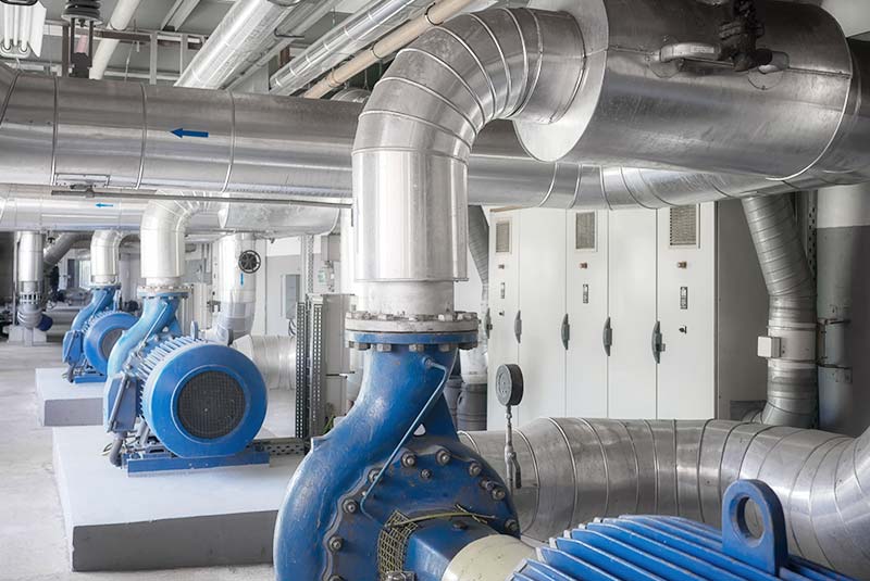
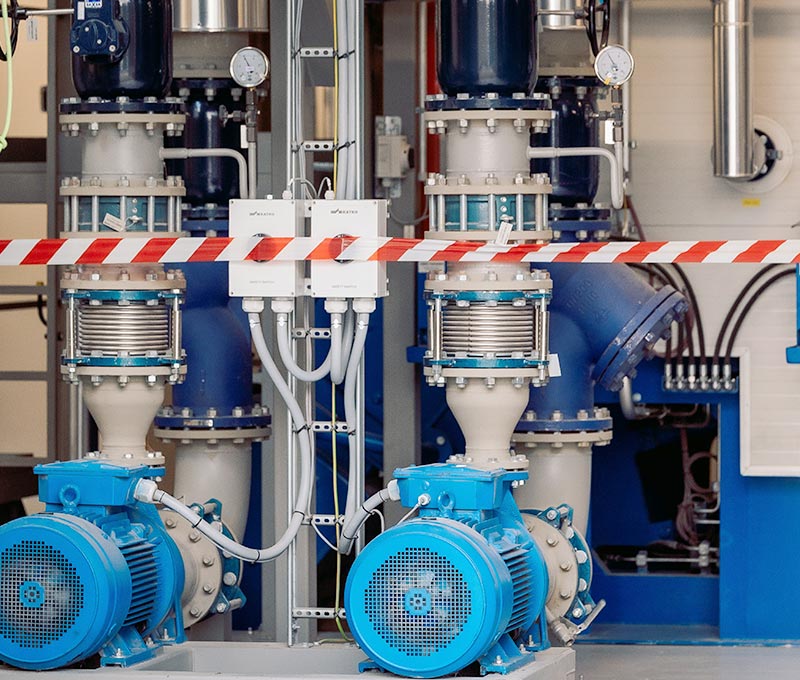
Centrifugal pumps, circulation pumps, process pumps, irrigation equipment, and other fluid-handling systems commonly use three phase motors.
Important selection factors include pump power demand, operating speed, starting method, duty cycle, environmental conditions, and whether variable-speed operation is required.
2. Fans and Ventilation Systems
Industrial fans, blowers, cooling equipment, and ventilation systems often operate for long periods.
Motor efficiency, vibration, noise, temperature rise, bearing condition, and speed control can therefore become particularly important.
3. Compressors
Compressors may require greater attention to starting torque and acceleration.
Motor selection should account for compressor type, starting arrangement, load condition, start-stop frequency, and expected operating duty.
4. Conveyors
Conveyor motors must accelerate both the conveying system and the material being transported.
Load weight, conveyor length, transmission ratio, starting characteristics, duty cycle, speed, and braking requirements should all be considered.
5. Machine Tools
Machine tools may require stable operation, repeated starts, reversing, braking, or integration with an automation system.
Motor characteristics should therefore be selected according to the machine operating cycle.
6. Industrial Automation
Automated machinery may combine induction motors with variable-frequency drives, PLCs, sensors, and process-control systems.
The motor becomes one component of a wider drive system, making compatibility between the motor, control method, mechanical load, and operating range especially important.
The site’s existing industrial motor application solutions provide a useful starting point for evaluating motors according to the driven equipment rather than treating every industrial load in the same way.
How to Select a Three Phase Induction Motor
A motor should not be selected according to rated power alone.
Two machines may both require a 15 kW motor while having completely different starting, speed, torque, cooling, and duty requirements.
The following factors should normally be reviewed.
| Selection factor | What to check |
|---|---|
| Rated power | Actual mechanical power required by the equipment |
| Voltage | Compatibility with the available power supply |
| Frequency | Usually evaluated together with required motor speed |
| Pole number | Determines the basic synchronous speed |
| Rated speed | Must match the driven equipment |
| Starting torque | Important for higher-load starting conditions |
| Efficiency | Important for long operating periods |
| IP protection | Depends on dust, moisture and installation environment |
| Insulation | Must support thermal and electrical conditions |
| Mounting | Must match the machine structure |
| Duty cycle | Continuous and frequent-start loads differ |
| Speed control | Determines whether VFD operation may be required |
The selection process should therefore begin with the driven machine.
For a pump, engineers may focus on flow demand, operating point, shaft power, and speed control.
For a conveyor, starting load and acceleration may be more important.
For a compressor, starting torque and operating cycle can be critical.
For an industrial fan, long running hours and variable airflow demand may make efficiency and speed control higher priorities.
Fixed Speed or Variable Speed?
A standard three phase induction motor connected directly to a fixed-frequency power supply operates within a relatively narrow speed range determined by frequency, pole number, and slip.
However, many modern industrial systems need adjustable speed.
A variable-frequency drive can control motor speed by changing the frequency and voltage supplied to the motor.
This can be useful in pumps and fans where process demand varies. Instead of operating continuously at one fixed speed, the motor-drive system can adjust output according to system requirements.
Variable-speed operation should nevertheless be considered during motor selection.
At lower speeds, a shaft-mounted cooling fan may move less air. Converter operation can also introduce additional electrical considerations, while the required torque range can vary between applications.
The motor and drive should therefore be evaluated as a complete system rather than assuming that any standard induction motor can operate over any speed range.
Three Phase Induction Motor vs Synchronous Motor
Three phase induction motors and synchronous motors both use rotating magnetic fields, but their rotor behavior differs.
In an induction motor, current is induced in the rotor by relative movement between the stator magnetic field and rotor. The rotor therefore normally operates with slip.
In a synchronous motor, rotor speed is synchronized with the rotating magnetic field during normal steady-state operation.
Permanent magnet synchronous motors use permanent magnets in the rotor and are commonly paired with electronic control systems.
Neither motor type should automatically be considered superior for every industrial application.
Induction motors are widely used where robust construction, mature technology, broad application compatibility, and straightforward operation are priorities.
Permanent magnet synchronous motors may be considered where system requirements place greater emphasis on efficiency, power density, torque characteristics, or advanced variable-speed control.
The correct choice depends on the machine and complete drive system.
What Information Is Needed Before Ordering a Motor?
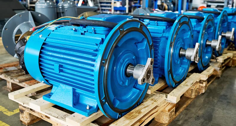
Providing complete technical information helps reduce the risk of selecting a motor that is electrically compatible but mechanically or operationally unsuitable.
For a new application, useful information normally includes:
- Required power
- Voltage
- Frequency
- Number of phases
- Required speed
- Driven equipment
- Starting characteristics
- Duty cycle
- Mounting arrangement
- Operating environment
- Required protection level
- Variable-speed requirements
For motor replacement projects, the existing nameplate can provide important information.
Frame size, shaft diameter, shaft length, mounting dimensions, connection arrangement, and rotation requirements should also be checked.
Applications involving unusual voltage, high ambient temperature, humidity, dust, frequent starts, restricted installation space, or special shaft requirements may need further engineering evaluation before a final motor configuration is selected.
Conclusion
A three phase induction motor uses a three-phase AC supply to create a rotating magnetic field in the stator. This field induces current in the rotor, and the interaction between the two magnetic fields produces mechanical torque.
Its relatively simple construction, broad range of configurations, and suitability for industrial duty explain why this motor type is widely used in pumps, fans, compressors, conveyors, machinery, and automation systems.
However, understanding what is a three phase induction motor is only the first step toward correct motor selection.
Rated power, voltage, frequency, number of poles, speed, torque, efficiency, protection level, insulation, mounting arrangement, duty cycle, and operating environment all need to be considered together.
A motor selected around the real operating requirements of the machine is more likely to provide stable and reliable performance than one selected only according to power rating.
FAQ
Is a three phase induction motor the same as an asynchronous motor?
Yes, the terms are commonly used to describe the same operating principle. The rotor normally runs slightly below the synchronous speed of the stator’s rotating magnetic field. This difference is called slip and enables the induction process required to produce rotor current and torque.
Why does a three phase induction motor need slip?
Slip creates relative movement between the rotating stator magnetic field and the rotor conductors. This relative movement induces rotor current. The resulting rotor magnetic field interacts with the stator field to generate torque, so some slip is required during normal loaded operation.
What determines the speed of a three phase induction motor?
Supply frequency and the number of motor poles determine synchronous speed. Actual rotor speed is slightly lower because of slip. Motor load can also affect the actual operating speed, while variable-frequency drives may be used when a wider adjustable-speed range is required.
What equipment commonly uses three phase induction motors?
Common applications include pumps, industrial fans, compressors, conveyors, ventilation systems, machine tools, processing machinery, and automated production equipment. The appropriate motor configuration depends on the mechanical load, operating environment, duty cycle, and required speed.
How do I choose the correct three phase induction motor?
Start with the requirements of the driven machine. Confirm power, voltage, frequency, speed, starting torque, operating duty, mounting arrangement, environmental conditions, and speed-control requirements. Replacement projects should also compare the existing frame size, shaft dimensions, mounting dimensions, and nameplate data.
Need Help Selecting the Right Three Phase Motor?
Selecting an industrial motor involves more than matching a power rating. The motor should be evaluated according to the actual load, power supply, speed, operating environment, mounting arrangement, and duty conditions.
For pumps, fans, compressors, conveyors, industrial machinery, or replacement projects, provide the required motor type, power, voltage, frequency, speed, application, mounting method, and working conditions through the Contact Us page so the appropriate motor configuration can be evaluated.