Table of Contents
A PMSM motor that is too small can overheat or fail to accelerate the machine. A PMSM motor selected with an unexplained margin can create unnecessary purchase cost and operate far from its intended duty. The useful starting point is the driven machine’s demand, including the worst credible operating condition.
For TYP permanent magnet motors, the decision centers on required shaft output and overload margin. This guide connects that question to converter-fed permanent magnet drive projects and the information an equipment buyer needs before approving a PMSM motor. The result should be a duty-point schedule and a supplier-confirmed torque margin, with the installation conditions visible to both the machine builder and the PMSM motor supplier.
The PMSM motor decision for this project
The first risk is selecting output from the old nameplate without establishing the driven load. In a project involving industrial machinery with a defined speed and torque envelope, that risk needs to be checked against the actual equipment duty. A product family is a useful way to shortlist an option, but the selected PMSM motor still needs an agreed operating requirement.
A permanent magnet synchronous motor uses rotor magnets and a rotating stator field. Its control requirements differ from those of a cage induction motor. The drive must support the PMSM motor technology and the required starting, acceleration, running and stopping behavior.
Sizing for the Real Load: the engineering method
Build a load schedule before choosing a frame. List the shaft speed, continuous torque, short-duration peak and time spent at each condition. Distinguish a process requirement from an allowance added by a previous designer. If the old PMSM motor repeatedly operated below its rating, that fact alone does not prove the new motor can be smaller. Starting torque, inertia, ambient temperature and protective coordination still need review.
For a rotating load, mechanical power relates to torque and speed. Use P(kW) = T(N·m) × n(r/min) / 9550 as an engineering estimate with consistent units. This relationship calculates shaft output, not electrical input. It also does not establish how much torque the PMSM motor can produce during starting or above its base speed. Compare the calculated duty with the PMSM motor supplier’s continuous and transient limits.
What to confirm about TYP permanent magnet motors
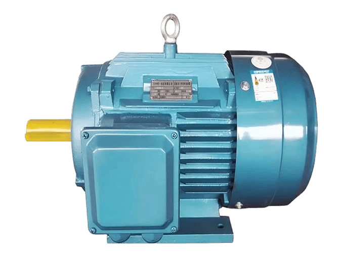
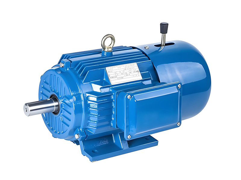
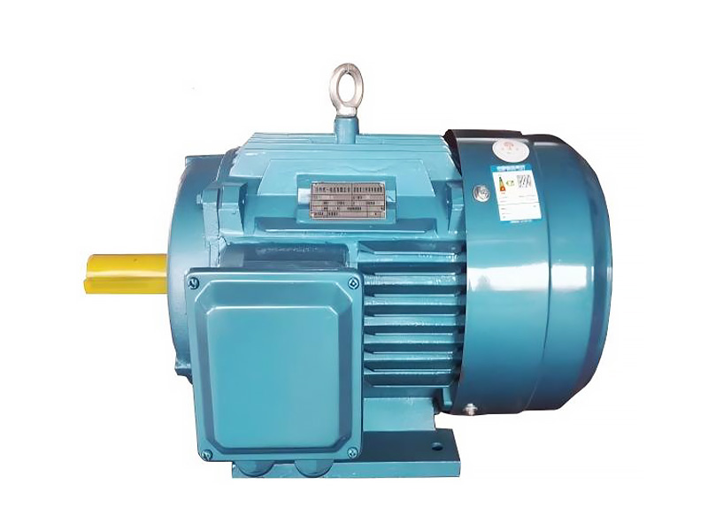
Tongyi lists a TYP variable-frequency three-phase permanent magnet synchronous motor. The online page provides model-specific ratings and speed ranges. Some headline efficiency and power-factor claims differ from individual table rows, so request confirmed values for the exact proposed model.
The product table includes a 3000 r/min family with a listed electrical frequency that should be interpreted through the selected rotor and control design. Do not apply an induction-motor pole assumption to infer compatibility. Have engineering confirm rated electrical frequency, speed and drive parameters together.
A rotating permanent magnet motor can generate voltage even when the supply is disconnected. The isolation and maintenance procedure must account for rotation driven by the machine or process. Shaft access, coupling arrangements and any back-driving condition belong in the engineering review.
Review Tongyi’s TYP permanent magnet motors information alongside the project requirement. For non-standard interfaces or operating conditions, use the engineering and customization service to resolve the offered configuration.
A worked screening example and its limits
Consider an illustrative machine requiring 30 N·m at 1450 r/min. The calculated shaft output is about 4.56 kW. The next PMSM motor selection step is not simply to round the result upward. Add the actual acceleration requirement, transmission losses where the torque was measured upstream, operating cycle and local thermal conditions. The example is a calculation method, not a Tongyi model recommendation.
For TYP permanent magnet motors, supplement this screening example with position feedback or sensorless requirements and back-driving and generated-voltage conditions. Compare the result with the confirmed operating envelope before choosing the final PMSM motor configuration.
Compare the available approaches for the PMSM motor
| Decision | Defined selection | Alternative to evaluate | Evidence needed |
|---|---|---|---|
| Drive approach | TYP PMSM with a compatible drive | cage induction motor with a matched inverter | whole-drive performance across the required duty map |
| Project objective | a duty-point schedule and a supplier-confirmed torque margin | A quotation based on incomplete operating assumptions | shaft torque, speed and duration |
| Electrical and controls | Supplier-confirmed motor and control data | Unconfirmed combination chosen by nominal power | rated electrical frequency and drive parameters; back-driving and generated-voltage conditions |
| Installation | Approved motor and mating-equipment drawings | Assumed fit from a similar frame | Interface dimensions, tolerances and service access |
| Release condition | Close documented deviations | Leave unresolved items visible | Accepted requirements tied to a model and revision |
Resolve this comparison using whole-drive performance across the required duty map, with shaft torque, speed and duration recorded under the same useful operating duty.
Build the model-specific technical schedule
Ask for rated current, torque, speed, electrical frequency, thermal limits and the parameters required by the chosen drive. Where a project relies on part-load savings, request operating-point data for the complete drive. Keep assumptions about converter losses separate from motor-only efficiency.
1. Continuous and peak torque-speed points.
2. Rated electrical frequency and drive parameters.
3. Position feedback or sensorless requirements.
4. Back-driving and generated-voltage conditions.
5. Motor and converter efficiency at actual loads.
Commissioning and acceptance sequence for the PMSM motor
Ask the equipment designer to identify the source of each torque and speed value. Where measurements are possible, record normal and worst-duty data over a representative production cycle. Keep startup, steady running and abnormal process events separate. Agree the acceptable overload duration and recovery time with the PMSM motor supplier.
During acceptance, demonstrate useful machine output at the agreed load points and check that current, temperature and speed remain within the approved limits. Keep a record of the instruments and process condition. An unloaded test can establish rotation and basic function, but it cannot validate full-load sizing.
Resolve the remaining application questions
A useful load record identifies the measurement boundary. Torque measured at the process shaft must be translated through the gearbox or belt drive before it becomes a motor-shaft requirement. State whether the reported value includes transmission losses. Keep the efficiency assumption explicit instead of adding several unexplained margins at different stages.
For a variable process, list the lowest, normal and highest useful output rather than selecting only a maximum. The largest output may occur rarely, while continuous thermal loading is governed by another state. Ask which short-duration demand the PMSM motor can tolerate and how long it needs to recover. A peak PMSM motor rating without a duration is incomplete.
The engineering release should show the source of the load data, the selected PMSM motor rating and the unresolved uncertainty. If the machine has never been built, the prototype plan should test the assumption that most affects sizing. If it is an existing machine, collect a representative production record before assuming that the old PMSM motor’s rating describes the real demand.
Troubleshooting and changes after approval
Poor starting or unstable speed can reflect incorrect parameters, an unsuitable control mode, missing feedback or an unrealistic load demand. Capture the operating condition and drive fault record. Avoid repeated uncontrolled restarts that could add thermal stress without clarifying the cause.
Do not assume that a standard induction-motor drive or direct line starting is suitable. Compatibility must be confirmed for the exact TYP model and control arrangement.
Prepare the final inquiry and evidence file for the PMSM motor
Send Tongyi the equipment description, the required shaft output and overload margin requirement and the five technical items above. The required outcome is a duty-point schedule and a supplier-confirmed torque margin. Keep the engineering scope as a complete permanent magnet drive evaluation rather than a motor-only substitution.
For broader technical context, consult U.S. Department of Energy motor and drive systems sourcebook. Use the applicable project requirements and model-specific supplier documents to make the final selection.
Ready to discuss the PMSM motor requirement? Share your load, supply, installation drawing and the required shaft output and overload margin target with Xuzhou Tongyi Motor. Ask for a model-specific technical review and quotation that addresses the open items in your PMSM motor specification.
Frequently asked questions
What information is needed for this PMSM motor selection?
Provide the equipment duty and the required shaft output and overload margin, together with continuous and peak torque-speed points and position feedback or sensorless requirements. Ask the supplier to confirm a specific configuration.
What should be checked first for TYP permanent magnet motors?
Does the chosen converter explicitly support this PMSM? Resolve this against the actual load and installation. The answer should be traceable to the offered rating or drawing.
Can a standard PMSM motor be substituted directly?
Only after the rating, interface, controls and operating conditions have been checked. For this project, whole-drive performance across the required duty map is central to the comparison.
What evidence supports sizing for the real load?
Obtain a duty-point schedule and a supplier-confirmed torque margin. Record shaft torque, speed and duration under the agreed duty, and identify any requirement that still needs site verification.
How can Tongyi review the requirement?
Send the duty schedule and current interface information through the inquiry form. Can the load rotate the shaft during isolation? Request a clear technical response before releasing the order.