Table of Contents
Introduction

The working of three phase induction motor systems is based on electromagnetic induction between the stator and rotor. When a balanced three-phase AC supply reaches the stator windings, it creates a rotating magnetic field. That field cuts across the rotor conductors, induces rotor current, and produces the electromagnetic torque needed to turn the shaft.
For industrial buyers and engineers, understanding the working of three phase induction motor equipment is useful because the operating principle explains many practical specifications. Motor speed, pole number, slip, starting current, torque, load behavior, efficiency, and variable-frequency operation are all connected to the same electromagnetic process.
The working of a three phase induction motor is simple in concept, but each stage affects how the motor performs in pumps, fans, compressors, conveyors, machine tools, and other industrial equipment. This guide breaks the working of three phase induction motor technology into seven key steps and explains how those steps influence selection and operation. Throughout the article, the working of three phase induction motor systems is connected directly to real industrial operating conditions.
What Starts the Working of Three Phase Induction Motor Systems?
The working of three phase induction motor systems begins at the stator. Three sets of windings are arranged around a laminated stator core and connected to a three-phase AC supply. Because the three currents are separated in phase, their magnetic effects combine to create a magnetic field that rotates around the stator.
This rotating magnetic field is the foundation of the working of three phase induction motor technology. It creates the relative magnetic motion needed to induce current in the rotor without a direct electrical supply to a squirrel-cage rotor.
The general principle of an induction motor is that rotor current is produced by electromagnetic induction from the stator magnetic field. This helps explain why the working of three phase induction motor equipment can be achieved with a robust rotor structure and without brushes or a commutator in common squirrel-cage designs.
This first principle is the basis for the working of three phase induction motor drives used across industrial machinery.
Step 1: Three-Phase Power Energizes the Stator
The first stage in the working of three phase induction motor equipment is supplying three-phase AC power to the stator windings. Each phase reaches its peak at a different moment. The combined effect is not a stationary magnetic field but a smoothly rotating one.
This feature is important because the working of three phase induction motor systems depends on continuous rotation of the stator field. A balanced supply helps create a more symmetrical magnetic condition, while serious voltage imbalance can increase current imbalance, heating, and vibration.
The stator winding design also determines important motor characteristics such as rated voltage, frequency, pole number, current, and thermal performance. For this reason, the working of three phase induction motor equipment is directly related to the electrical system for which the motor was designed.
A stable three-phase supply is therefore essential to the normal working of three phase induction motor systems.
Step 2: The Stator Creates a Rotating Magnetic Field
After the stator is energized, the working of three phase induction motor systems moves to the rotating magnetic field. Its theoretical speed is called synchronous speed.
Synchronous speed is calculated from supply frequency and the number of motor poles:
Synchronous speed = 120 × frequency ÷ number of poles
At 50 Hz, typical synchronous speeds are:
| Motor poles | Synchronous speed |
|---|---|
| 2 poles | 3,000 rpm |
| 4 poles | 1,500 rpm |
| 6 poles | 1,000 rpm |
| 8 poles | 750 rpm |
Understanding synchronous speed is essential to the working of three phase induction motor equipment because the rotor normally operates slightly below this value. The difference between field speed and rotor speed creates the relative motion needed for induction.
The number of poles therefore has a direct effect on the working of three phase induction motor applications. A high-speed pump may require a different pole configuration from a conveyor or machine designed for lower shaft speed.
Frequency and pole number are therefore basic variables in the working of three phase induction motor equipment.
Step 3: The Magnetic Field Induces Rotor Current
The third stage in the working of three phase induction motor systems takes place in the rotor. In a common squirrel-cage design, the rotor contains conductive bars connected by end rings. The rotor bars form a closed electrical path even though they are not directly wired to the external power supply.
As the rotating magnetic field moves relative to the rotor, it cuts across the rotor conductors. This changing magnetic condition induces an electromotive force and causes current to flow through the rotor bars.
This is the key induction process in the working of three phase induction motor technology. The stator receives electrical power directly, while the rotor receives the electromagnetic effect needed to create current.
At startup, the rotor is stationary, so the relative speed between the rotating field and rotor is high. This makes induction strong and allows the working of three phase induction motor equipment to develop starting torque.
Rotor induction is therefore a defining stage in the working of three phase induction motor systems.
Step 4: Rotor Current Produces Electromagnetic Torque
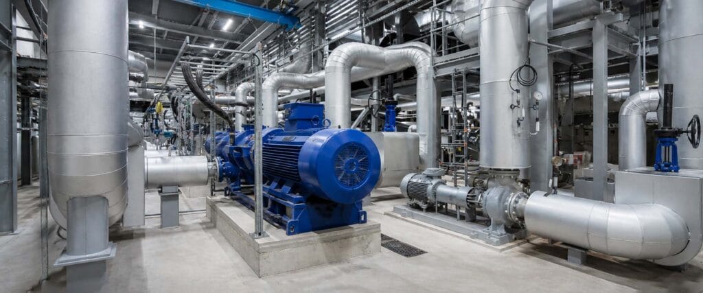
Once current flows in the rotor, the next stage in the working of three phase induction motor systems is torque production. Rotor current creates a magnetic effect that interacts with the rotating stator field.
The interaction produces electromagnetic force on the rotor conductors. That force creates torque, causing the rotor and shaft to begin turning in the same direction as the rotating magnetic field.
This torque-producing process is central to the working of three phase induction motor equipment. Electrical input power is converted into mechanical output that can drive a pump, fan, compressor, conveyor, gearbox, or industrial machine.
Different loads place different demands on torque. For this reason, understanding the working of three phase induction motor systems is especially useful when comparing motors for equipment with light starting loads and machines that need higher starting torque.
Torque production links the electromagnetic process directly to the practical working of three phase induction motor applications.
Step 5: The Rotor Accelerates Below Synchronous Speed
As the rotor accelerates, the working of three phase induction motor systems enters its normal running region. Rotor speed approaches synchronous speed but does not normally equal it while the motor is producing useful induction torque.
If the rotor reached exactly the same speed as the rotating field, there would be no relative motion between the field and rotor conductors. Without that relative motion, the induction process needed to maintain rotor current would be lost.
This is why the working of three phase induction motor equipment requires a small difference between magnetic-field speed and rotor speed. The difference is called slip.
For example, a 4-pole motor on a 50 Hz supply has a synchronous speed of 1,500 rpm. Its actual rated speed under load may be somewhat lower, depending on motor design and operating conditions.
Maintaining this speed difference is essential to the working of three phase induction motor equipment under load.
Step 6: Slip Changes as Mechanical Load Changes
Slip is one of the most important concepts in the working of three phase induction motor systems.
It can be calculated as:
Slip = (synchronous speed − rotor speed) ÷ synchronous speed × 100%
If a 4-pole, 50 Hz motor has a synchronous speed of 1,500 rpm and operates at 1,470 rpm, slip is approximately 2%.
In practical operation, the working of three phase induction motor equipment responds naturally to changing mechanical load. When the load increases, rotor speed may fall slightly. Slip increases, which strengthens the induction conditions needed for the motor to develop additional torque.
When the load decreases, rotor speed can move closer to synchronous speed and slip becomes smaller.
This relationship is a major reason the working of three phase induction motor systems suits many industrial machines with changing but controlled loads.
In other words, slip is not incidental; it is fundamental to the working of three phase induction motor technology.
Step 7: The Motor Reaches a Stable Operating Point
The final stage in the working of three phase induction motor operation is the balance between motor torque and load torque. Once acceleration is complete, the motor settles at a speed where developed torque is sufficient to drive the connected equipment and overcome internal losses.
If the load remains within the motor’s capability, the working of three phase induction motor equipment continues at a relatively stable speed. If the load rises, speed drops slightly and the motor develops more torque. If the load falls, the rotor runs closer to synchronous speed.
However, the working of three phase induction motor systems has practical limits. Excessive mechanical load can lead to high current, excessive temperature rise, reduced speed, and possible damage.
Stable operation depends on matching the working of three phase induction motor equipment to the torque demand of the driven machine.
How the Working Principle Affects Motor Speed
The working of three phase induction motor systems explains why motor speed cannot be judged from rated power alone. Frequency and pole number determine synchronous speed, while slip determines the difference between synchronous speed and actual rotor speed.
For example, two motors may both be rated at 15 kW but have different pole numbers and therefore different operating speeds. This directly changes the working of three phase induction motor equipment.
A 2-pole design is suited to a different speed range from a 4-pole or 6-pole design.
This is why the working of three phase induction motor equipment must be considered together with the driven machine. Pumps, fans, conveyors, and compressors may require different speed and torque characteristics even when rated power is similar.
Speed selection is therefore inseparable from the working of three phase induction motor systems.
The range of industrial electric motors used in machinery includes different pole configurations, efficiency levels, mounting arrangements, and application characteristics. Selecting among them starts with the required load and speed rather than power alone.
How Load Affects the Working of Three Phase Induction Motor
The working of three phase induction motor systems is closely connected to load behavior. A centrifugal fan does not impose the same torque-speed demand as a conveyor, compressor, or machine tool.
When load rises within the designed operating range, the motor normally experiences a small reduction in rotor speed. That increases slip and allows the motor to produce more torque. This automatic response is part of the working of three phase induction motor equipment.
If the motor is badly undersized, however, the load may demand more torque than the motor can provide continuously. Current and temperature can increase, and speed may fall excessively.
Correct motor selection therefore requires information about the driven machine. This information supports the correct working of three phase induction motor systems.
Load behavior is one of the most important practical influences on the working of three phase induction motor equipment.
The site’s industrial motor applications illustrate why operating conditions for pumps, fans, and machinery should be evaluated separately rather than treating every load as identical.
How Efficiency Relates to Motor Working
The working of three phase induction motor equipment includes several unavoidable energy losses. Stator winding resistance produces copper losses, rotor current produces rotor losses, changing magnetic fields create core losses, and bearings and ventilation create mechanical losses.
Motor efficiency represents the proportion of electrical input power converted into useful mechanical shaft output. Efficiency is another outcome of the working of three phase induction motor systems.
The working of three phase induction motor systems can therefore be improved through optimized electromagnetic design, conductor sizing, magnetic materials, rotor design, cooling, and mechanical construction.
Efficiency becomes particularly important in motors that operate for long periods. Pumps, fans, and production machinery may run for many hours each day, so both motor efficiency and correct loading deserve attention.
An oversized motor is not automatically a better choice. Proper loading helps the working of three phase induction motor systems remain within the intended thermal and efficiency range.
The working of three phase induction motor equipment should be matched to the actual operating point so that power, torque, thermal behavior, and efficiency are considered together.
Direct-on-Line Starting and Motor Operation
The working of three phase induction motor systems also explains why a standard three-phase motor can be self-starting. At standstill, the rotating stator field moves relative to the stationary rotor, inducing rotor current and producing starting torque.
During direct-on-line starting, the full supply voltage is applied to the motor. This can produce a relatively high starting current, which may be acceptable for smaller motors or suitable electrical systems but may require another starting method in other installations.
Star-delta starters, soft starters, and variable-frequency drives can be used according to motor size, electrical network conditions, starting torque requirements, and machine behavior.
Each method influences the starting working of three phase induction motor equipment.
The starting method does not change the fundamental working of three phase induction motor technology. It only changes how the working of three phase induction motor equipment is managed during acceleration.
How a VFD Changes Motor Operation
The working of three phase induction motor systems can also be controlled with a variable-frequency drive. A VFD changes the frequency supplied to the motor, which changes the synchronous speed of the rotating magnetic field.
This allows the motor to operate over an adjustable speed range when the motor and application are suitable for variable-frequency control.
VFD control changes speed while preserving the working of three phase induction motor principles.
For pumps and fans, variable speed can help match motor output to process demand. For conveyors and production equipment, it can provide controlled acceleration and speed adjustment.
Even with a VFD, the basic working of three phase induction motor equipment remains the same: the stator creates a rotating magnetic field, the field induces rotor current, slip exists between field and rotor speed, and electromagnetic interaction produces torque.
Low-speed cooling, insulation, torque demand, operating frequency range, and bearing conditions should still be considered when selecting a motor for VFD operation.
These factors influence the working of three phase induction motor systems outside normal fixed-frequency conditions.
What Information Matters When Selecting a Motor?
Understanding the working of three phase induction motor technology makes it easier to see why several specifications must be considered together.
| Selection factor | Why it matters |
|---|---|
| Rated power | Must match the mechanical demand of the equipment |
| Voltage | Must match the electrical supply and winding design |
| Frequency | Affects synchronous speed |
| Pole number | Determines the basic motor speed range |
| Rated speed | Must suit the driven machine |
| Starting torque | Important for difficult-starting loads |
| Duty cycle | Affects thermal loading |
| Efficiency | Influences electrical losses during operation |
| Protection level | Must suit dust, moisture, and environment |
| Mounting | Must match the mechanical installation |
| VFD operation | Affects speed range, cooling, and control |
The working of three phase induction motor systems is therefore not separate from motor selection. Correct selection protects the intended working of three phase induction motor equipment.
Each electrical and mechanical specification changes how the motor interacts with its load.
For replacement projects, nameplate information, frame size, shaft dimensions, mounting arrangement, direction of rotation, and actual load should also be checked before a new motor is selected.
These details help preserve the expected working of three phase induction motor systems.
Why the Working Principle Matters for Industrial Buyers
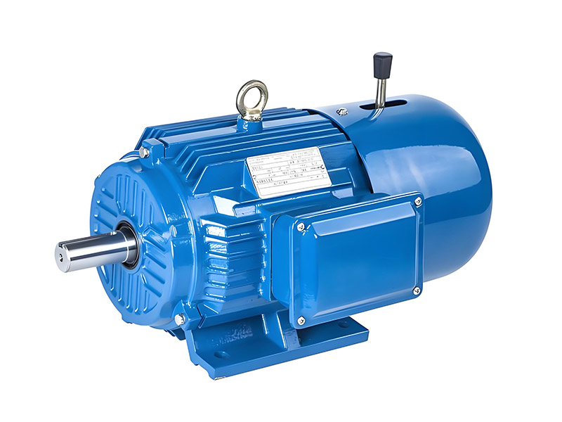
The working of three phase induction motor equipment helps buyers understand why two motors with similar power ratings may still behave differently in operation.
Pole number changes speed. Motor construction affects efficiency and thermal behavior. Starting conditions influence current and torque. Load characteristics influence slip. Environmental conditions influence enclosure and cooling requirements.
Understanding the working of three phase induction motor systems therefore helps prevent selection based only on one specification such as kW or horsepower.
For pump applications, speed and continuous duty may be major considerations. For conveyors, starting torque may become more important. For compressors, acceleration and operating load can be critical. For fans, long running hours and variable-speed control may deserve greater attention.
The working of three phase induction motor technology should always be considered together with the real machine rather than as an isolated electrical concept.
Conclusion
The working of three phase induction motor systems can be understood as a seven-stage electromagnetic process. Three-phase power energizes the stator, the stator creates a rotating magnetic field, the field induces current in the rotor, rotor current produces electromagnetic torque, the rotor accelerates, slip allows continued induction, and the motor reaches a stable operating point with the connected load.
The working of a three phase induction motor also explains several practical characteristics: the rotor runs below synchronous speed, slip changes with load, pole number affects speed, starting conditions affect current and torque, and efficiency depends on electrical and mechanical losses.
For industrial applications, understanding the working of three phase induction motor equipment helps buyers compare motors more accurately. Power, voltage, frequency, pole number, rated speed, torque, duty, protection, mounting, cooling, and control method should all be matched to the actual machine.
The working of three phase induction motor systems is therefore not simply theoretical knowledge. It provides the technical foundation for selecting a motor that can operate reliably under the required load, speed, duty, and environmental conditions.
FAQ
Why is the working of three phase induction motor based on electromagnetic induction?
The working of three phase induction motor equipment depends on the rotating stator magnetic field cutting across rotor conductors. This relative magnetic movement induces rotor current without a direct external electrical connection to a squirrel-cage rotor. The induced current then creates the electromagnetic interaction needed to produce torque.
Why does the rotor run below synchronous speed?
The working of three phase induction motor systems requires relative movement between the stator magnetic field and rotor. If the rotor reached synchronous speed, this relative movement would disappear and normal induction torque could not be maintained. The speed difference is known as slip.
What happens when the motor load increases?
During the working of three phase induction motor equipment, an increase in load usually causes a small decrease in rotor speed. Slip increases, allowing the motor to develop more electromagnetic torque. This continues until a new balance is reached, provided the load remains within the motor’s operating capability.
Does pole number affect the working of three phase induction motor systems?
Yes. Pole number changes synchronous speed at a given supply frequency. A motor with more poles has a lower synchronous speed. The working of three phase induction motor equipment therefore needs to be evaluated together with the speed requirements of the driven machine.
Can a VFD change the speed of a three phase induction motor?
Yes. A VFD changes supply frequency, which changes the speed of the rotating stator magnetic field. The fundamental working of three phase induction motor systems remains based on induction and slip, but the operating speed can be adjusted within a range suitable for the motor and application.
Need Help Matching Motor Operation to Your Equipment?
The working of three phase induction motor technology is closely connected to load, speed, torque, power supply, mounting, and duty conditions. Before selecting a motor, confirm the required power, voltage, frequency, speed, application, starting characteristics, working environment, and control method.