Table of Contents
Stopping a moving machine and holding a stationary load are separate engineering functions. A brake motor or brake arrangement must address the energy, torque and control sequence required by each. A short stop time can create a high thermal or electrical demand.
For YEJ electromagnetic brake motors, the decision centers on deceleration energy and load-holding behavior. This guide connects that question to controlled stopping and load-holding applications and the information an equipment buyer needs before approving a brake motor. The result should be a stopping-energy and holding-function specification, with the installation conditions visible to both the machine builder and the brake motor supplier.
The brake motor decision for this project
The first risk is using holding torque as proof of repetitive dynamic braking capacity. In a project involving conveyors, indexing machinery and equipment with defined stopping requirements, that risk needs to be checked against the actual equipment duty. A product family is a useful way to shortlist an option, but the selected unit still needs an agreed operating requirement.
A brake motor brake provides a mechanical braking function whose capacity must match the application. Holding torque, dynamic stopping energy, stopping frequency and response time are different requirements. A brake selected only from the brake motor kilowatt rating may not meet the machine’s duty.
Separating Stopping and Holding Duty: the engineering method
Rotational kinetic energy is one-half of equivalent inertia multiplied by angular speed squared. Determine where that energy goes during stopping: process losses, a mechanical brake, a drive braking resistor or a regenerative arrangement. Add potential energy for applicable descending or back-driving loads.
Holding torque does not establish dynamic stopping capacity. Likewise, a drive’s normal deceleration control does not automatically provide the required holding or safety function. Define the roles explicitly and coordinate brake motor, brake, converter and machine protection.
What to confirm about YEJ electromagnetic brake motors
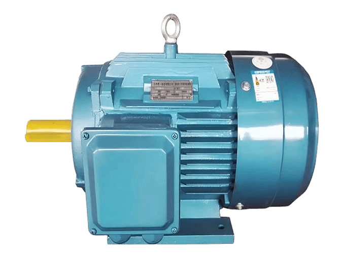
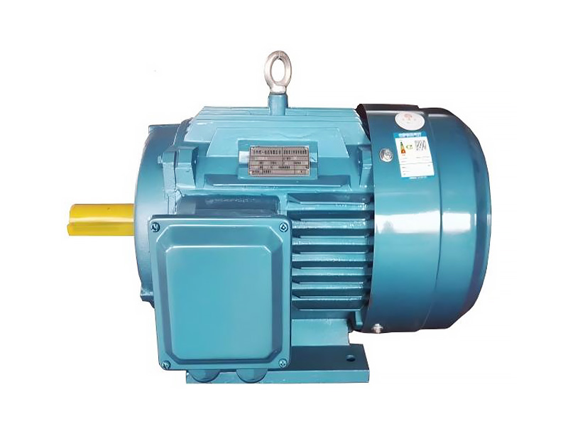
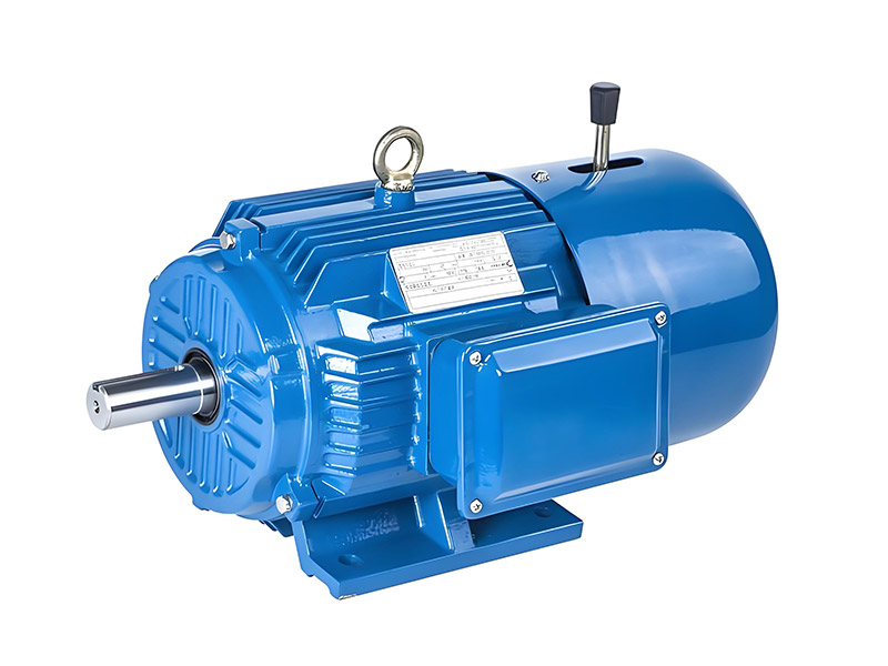
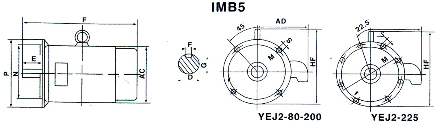
Tongyi lists a YEJ electromagnetic brake three-phase asynchronous motor. Its product page emphasizes frame-dependent contour and installation dimensions. The dimensional table helps plan machine integration, but it does not provide a complete braking performance brake motor specification.
The online YEJ page does not establish a model-specific stopping energy brake motor rating, brake voltage or permissible operating frequency. Request these values and the brake circuit documentation before comparing quotations. A suitable mounting drawing alone is insufficient evidence of stopping performance.
Repeated dynamic stops convert kinetic energy into heat in the braking system. The allowable energy per stop and average heat over the duty cycle both matter. A machine can hold a stationary load successfully yet exceed the brake’s thermal capacity during repetitive production stops.
Review Tongyi’s YEJ electromagnetic brake motors information alongside the project requirement. For non-standard interfaces or operating conditions, use the engineering and customization service to resolve the offered configuration.
A worked screening example and its limits
An illustrative 1 kg·m² rotating assembly at 1500 r/min stores about 12.3 kJ of kinetic energy. Repeating that stop ten times per minute represents a different heat duty from one occasional stop. Real brake motor selection must include the entire reflected inertia, process energy and the approved braking limits.
For YEJ electromagnetic brake motors, supplement this screening example with required stop time and stops per hour and brake supply and release sequence. Compare the result with the confirmed operating envelope before choosing the final brake motor configuration.
Compare the available approaches
| Decision | Defined selection | Alternative to evaluate | Evidence needed |
|---|---|---|---|
| Drive approach | brake motor with specified stopping duty | ordinary motor with an independently designed braking system | holding torque, stopping energy and control timing |
| Project objective | a stopping-energy and holding-function specification | A quotation based on incomplete operating assumptions | stop time, energy per event and cycle rate |
| Electrical and controls | Supplier-confirmed motor and control data | Unconfirmed combination chosen by nominal power | maximum speed at brake application; brake supply and release sequence |
| Installation | Approved motor and mating-equipment drawings | Assumed fit from a similar frame | Interface dimensions, tolerances and service access |
| Release condition | Close documented deviations | Leave unresolved items visible | Accepted requirements tied to a model and revision |
Resolve this comparison using holding torque, stopping energy and control timing, with stop time, energy per event and cycle rate recorded under the same useful operating duty.
Build the model-specific technical schedule
Coordinate brake motor power, brake release and drive deceleration. Releasing too late can force the brake motor to work against an applied brake, while applying too early can increase wear. Any safety-related stopping function requires a machine-level design and validation beyond a generic brake motor description.
1. Load inertia referred to the brake motor shaft.
2. Maximum speed at brake application.
3. Required stop time and stops per hour.
4. Brake supply and release sequence.
5. Holding load and required safety function.
Commissioning and acceptance sequence
State maximum speed, equivalent inertia, required stop time, stops per hour and any holding load. Request brake or drive energy limits and the permitted control sequence. Have the machine designer define any safety-related function and its validation.
At commissioning, measure stop performance under the agreed worst-duty condition and evaluate repeated-cycle behavior. Retain the final timing and settings. Do not claim that one successful stop proves indefinite repetitive stopping capacity.
Resolve the remaining application questions
Identify the stopping function required by the process before choosing the device that provides it. A normal production stop, power-loss holding and a safety-related stop can demand different arrangements. The machine designer should assign the role of the brake motor, drive, brake and any independent protection.
Energy accounting should include loads that add energy during the stop. A descending mass or a process that back-drives the shaft can increase the demand beyond rotational inertia alone. Ask where this energy is dissipated or returned and which component sets the permitted repetition rate.
Acceptance should examine both a demanding individual stop and the repeated production cycle. Record initial speed, load and stop time, and check the relevant thermal or wear limits. Keep the brake release and application timing with the accepted configuration so later controller changes do not alter the original duty unnoticed.
Troubleshooting and changes after approval
Dragging, inconsistent stops or a hot brake can indicate incomplete release, incorrect supply, worn friction parts or unsuitable sequencing. Record when the fault occurs in the cycle. Repeatedly adjusting mechanical clearances without checking electrical release behavior can hide the root cause.
A brake motor does not automatically constitute a validated emergency-stop, lifting or personnel-protection system. The machine designer must establish the required safety functions.
Prepare the final inquiry and evidence file
Send Tongyi the equipment description, the deceleration energy and load-holding behavior requirement and the five technical items above. The required outcome is a stopping-energy and holding-function brake motor specification. Keep the engineering scope as a stopping-duty brake motor specification with machine safety reviewed separately.
For broader technical context, consult U.S. Department of Energy motor and drive systems sourcebook. Use the applicable project requirements and model-specific supplier documents to make the final selection.
Ready to discuss the brake motor requirement? Share your load, supply, installation drawing and the deceleration energy and load-holding behavior target with Xuzhou Tongyi Motor. Ask for a model-specific technical review and quotation that addresses the open items in your brake motor specification.
Frequently asked questions
What information is needed for this brake motor selection?
Provide the equipment duty and the deceleration energy and load-holding behavior, together with load inertia referred to the motor shaft and required stop time and stops per hour. Ask the supplier to confirm a specific configuration.
What should be checked first for YEJ electromagnetic brake motors?
Is the brake intended for holding, dynamic stopping or both? Resolve this against the actual load and installation. The answer should be traceable to the offered rating or drawing.
Can a standard brake motor be substituted directly?
Only after the rating, interface, controls and operating conditions have been checked. For this project, holding torque, stopping energy and control timing is central to the comparison.
What evidence supports separating stopping and holding duty?
Obtain a stopping-energy and holding-function specification. Record stop time, energy per event and cycle rate under the agreed duty, and identify any requirement that still needs site verification.
How can Tongyi review the requirement?
Send the duty schedule and current interface information through the inquiry form. What stopping energy and cycle rate are permitted? Request a clear technical response before releasing the order.